
The hardware
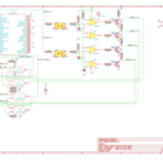
 I have designed an add on circuit board for the Raspberry Pi to control stall motor turnout motors. This board uses a quad op-amp circuit to drive a quad output transistor to drive the motors. It also features a 74AHCT00 Quad 2-input Nand Gate IC, wired as a pair of RS Flip-Flops to debounce switch contacts used to sense the position of the points. This small board uses 4 of the ‘Pis GPIO pins to control and sense two stall motors:
- WiringPi 0, BCM 17
- Motor Select 1: select the position of stall motor 1
- WiringPi 1, BCM 18
- Motor Select 2: select the position of stall motor 2
- WiringPi 2, BCM 27
- Point Sense 1: return the state of the points for stall motor 1
- WiringPi 3, BCM 22
- Point Sense 2: return the state of the points for stall motor 2
 The stall motors are optically isolated from the Pi and use their own 12-16 Volt power. The outputs are through output transistors that can handle up to 1A each, far more than enough to handle any available stall motors, including pairs wired in parallel (as for cross-overs). The point sense inputs expect a SPDT switch to sense the point position (one pole of the built in switch contacts in a Tortoise can serve this purpose).
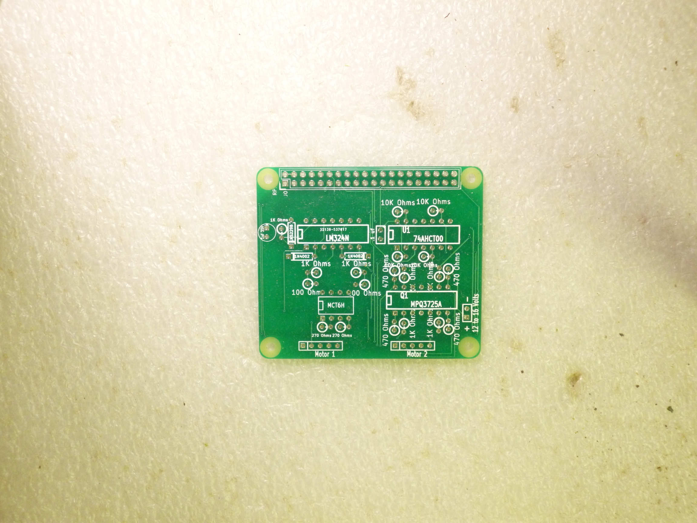 I had a batch of unpopulated boards made through ALLPCB (www.allpcb.com). This is a great way to get prototype or test runs of PC boards made. It is low-cost, fast, and it is an easy process. The boards were quickly made and were shipped quickly.
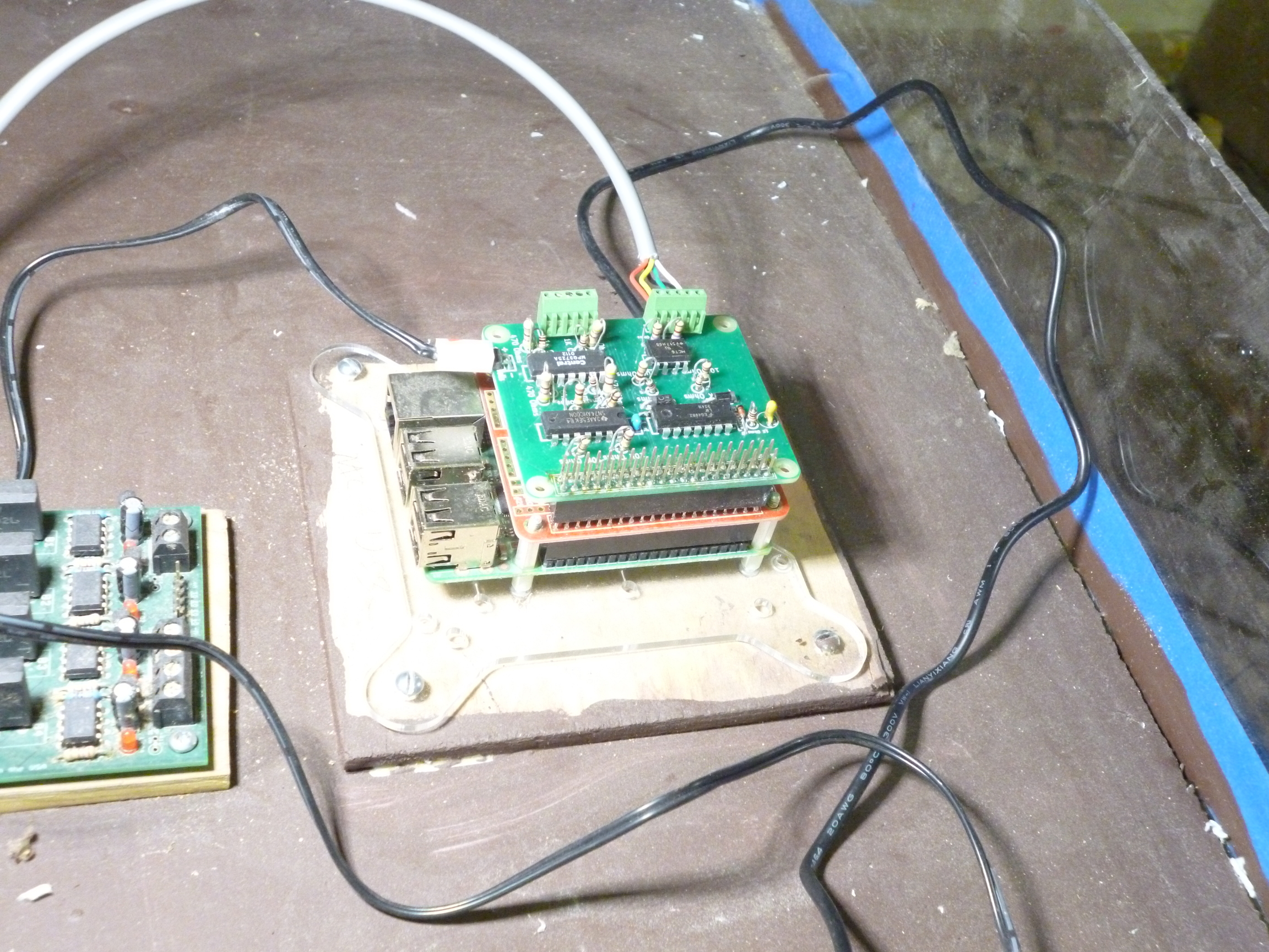
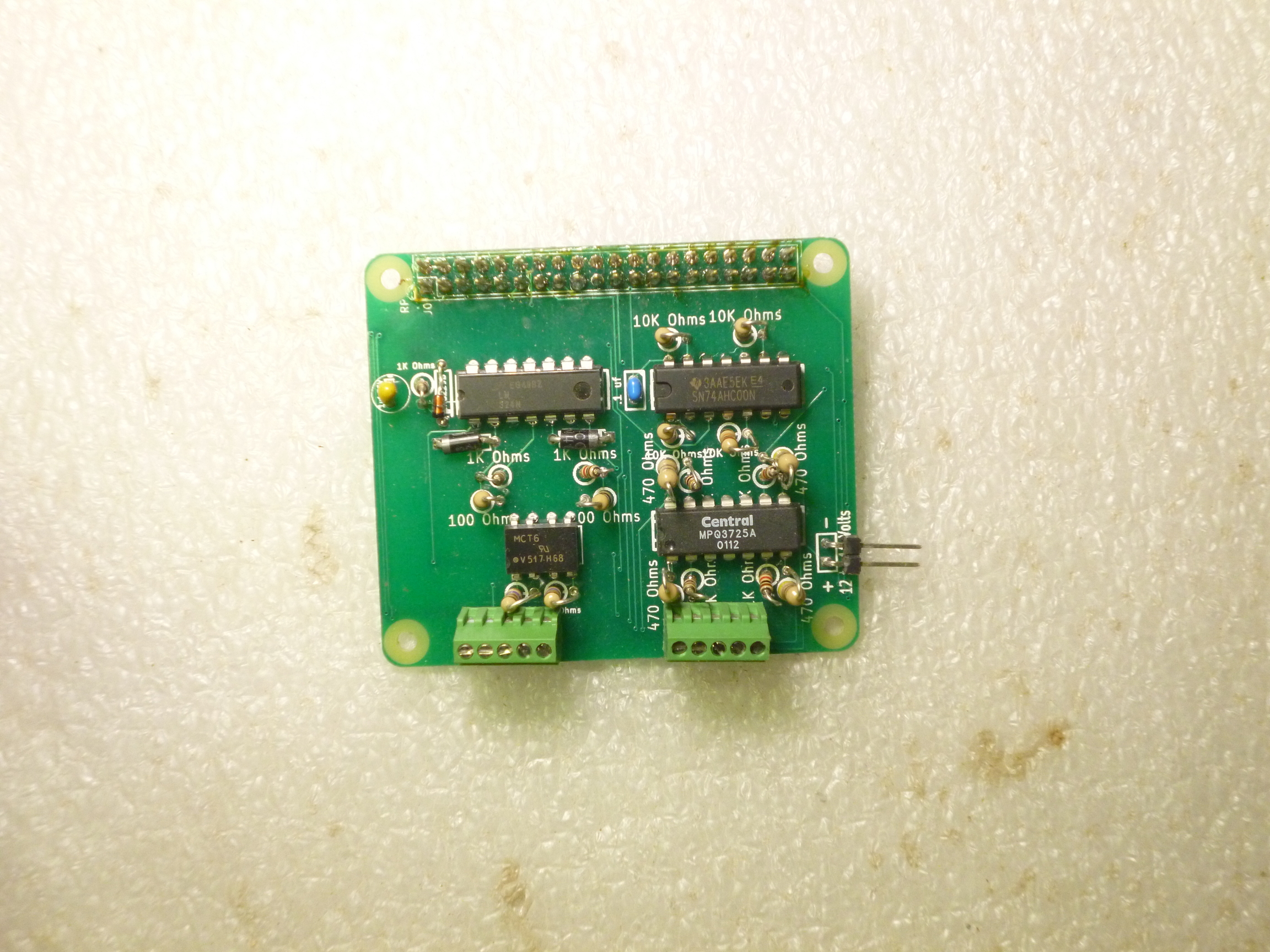 With the parts I ordered from Mouser, I quickly assembled one of the boards. I installed it on a Raspberry Pi 3B (sirtopmhat). Once I installed it an added a 12Volt power supply for the Tortoise I was able to test it. And it worked! Sir Top’m Hat is now working for the railroad!
The Software
On the software side, I am using the OpenLCB_PiGPIO program from Deepwoods Software’s Model Railroad System to manage this little board. There is a sample XML configuration file on GitHub with the circuit board. I am also using a CTC Panel created with the Model Railroad System’s Dispatcher program. The CTC Panel is a simple one my Raspberry Pi Junction demo layout, which consists of a short section of main line track with a spur leading to the Mad Hatter Pi Shop (a modified 50’s style drive in restaurant).
The OpenLCB_PiGPIO and the CTC Panel program exchange LCC event reports, with the CTC panel sending events to activate the turnout motor to change the point position and the OpenLCB_PiGPIO sending event reports to indicate changes in the point position to the CTC Panel program so the CTC Panel program can update its display of the turnout. I have another batch of PCBs on order that will have the logic to interface with the block occupancy detectors. This will allow me to implement the logic to drive the signals and also control the lights in the Mad Hatter’s Pi Shop.