
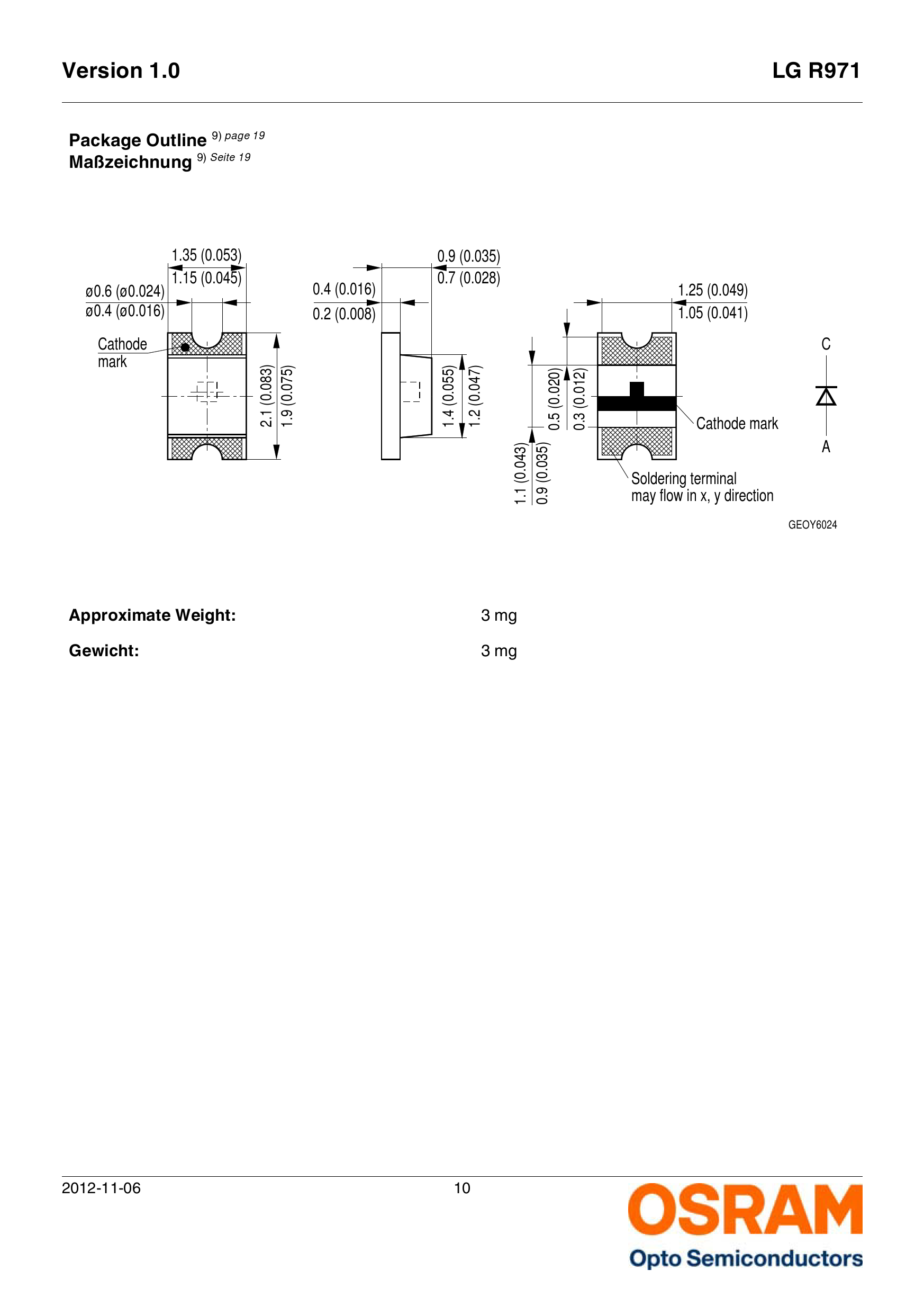
 The next step is to assemble the signal targets. I used 2mm x 1.25mm chip LEDs, made by Osram and sold by Mouser (part numbers Green: 720-LGR971-KN-1, Yellow: 720-LYR976-PS-36, and Super Red: 720-LSR976-NR-1). These are $.10 each in single quantities and the price goes down to about five and a half cents each in quantities of 100. If you decide to use chip LEDs instead of regular 3mm LEDs with leads, be sure to get some extras, because you will likely loose one or two.
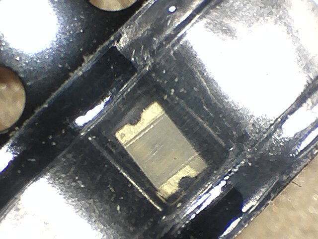
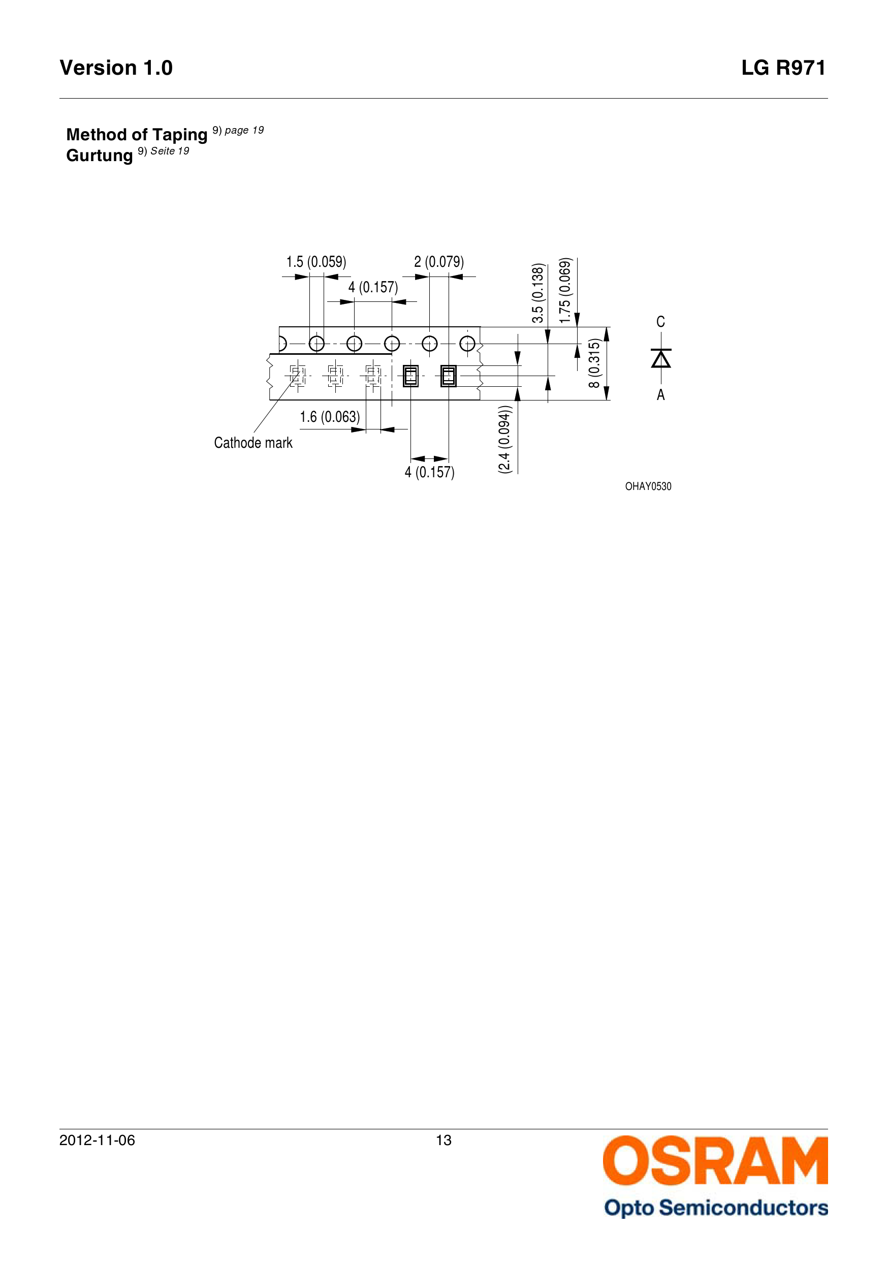 These devices come on a tape carrier. This is something normally meant to go in a robot feeding device that places the chips on circuit boards in robotic factory. To handle these devices by hand you will need to make a tool to hold them. I made a tool from a standard round toothpick. I used a razor saw to cut one of the end points off, sanded cut flat and applied a dab of Detail Tack (available from Micro-Mark for $7.95). This stuff dries clear and remains tacky (sticky). This lets you pick up the chips from their tape carrier and hold them in place as you re-flow the solder to secure them to the circuit board.
You will also need a supply of wire wrap wire in a number of colors (this is available from DigiKey), a supply of cut off resistor leads (or really any small solid bare wired cut into pieces about 1/2 to 3/4 inches long), and a piece of Strip-board two foil strips wide (.2 inches / 5mm) that is long enough to make little circuit boards for your targets — you will need 6 holes for 3 color targets, 4 holes for 2 color targets, and 2 holes for single color targets. I also used a block of foam as a work surface, since it let me push the resistor leads into it.
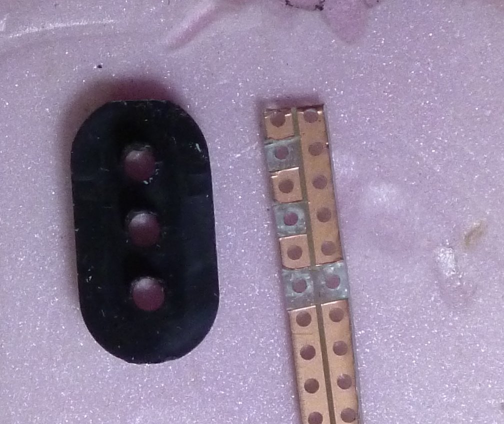
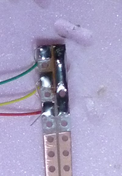 The first step is to remove some of the foil. One side is the common side (cathode end) and the other is for one-of connections (anode). The common / cathode is connected with a resistor lead that will be soldered to the brass tube the signal targets will be mounted to. The anode side will be connected with wire wrap wire, one per chip and color coded (I used green, yellow, and red for the upper head and blue, white, and black for the lower head). Once the foil bits have been removed, strip and feed the wire wrap wire on one side and push the resistor lead through a hole on the other side and then solder the wires. Be sure to spread a thin layer of solder down the length of the common side.
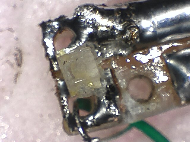 Now we can solder on the LED chips. The carrier tape has a clear cover strip over the top. Carefully peel this back (a hobby knife can help with this). Only peel back one chip at a time. Once the cover strip has been peeled back the chips can very easily bounce out and promptly vanish! Or at least become disorientated… It is important to remember that the side of the tape with the holes is the cathode end, so you should keep the hole side oriented to the same side as the common side of the circuit board. Once you have peeled the cover off one chip, use your pickup tool (toothpick with flattened end with detail tack on it) to pick up the chip and being careful not to twist the toothpick position the chip on the circuit board. Using a small electronics soldering iron briefly reheat the solder on each side to secure the chip. You will want to wait for the solder to cool on the first side before reheating the second side. Be sure to inspect your work and test the chip before continuing on to the next chip. You will probably want to do all of chips of each color before moving on to the next color, since there is no obvious way to tell which color a chip is.
Once the chips have been soldered to the circuit board, each target’s circuit board can be cut off the strip and that target’s circuit board can be glued to the back of the target with a CA (superglue) adhesive. Finally, the circuit board can be covered with opaque black paint or LIQUID ELECTRICAL TAPE (available from Micro-Mark). The targets can now be assembled with their brackets to the signal masts (3/32 inch brass tubing). Route the wire wrap wires inside the brass tubing (use a 1mm drill to drill holes near where the wires come off the circuit boards). The common lead (the resistor lead wire) can be soldered to the brass tubing and an additional wire wrap wire soldered to the end of the tube.
Continuing with Model RR signals with an Arduino, Programming the Arduino.