
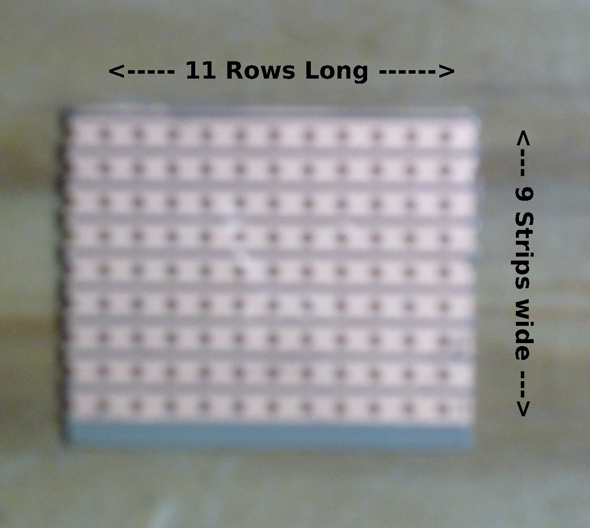
Signal Connector Board, bare
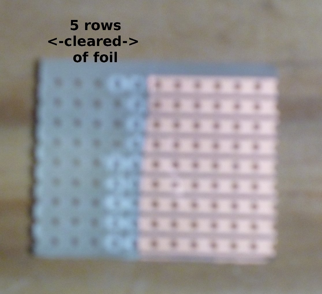
Signal Connector Board, copper removed
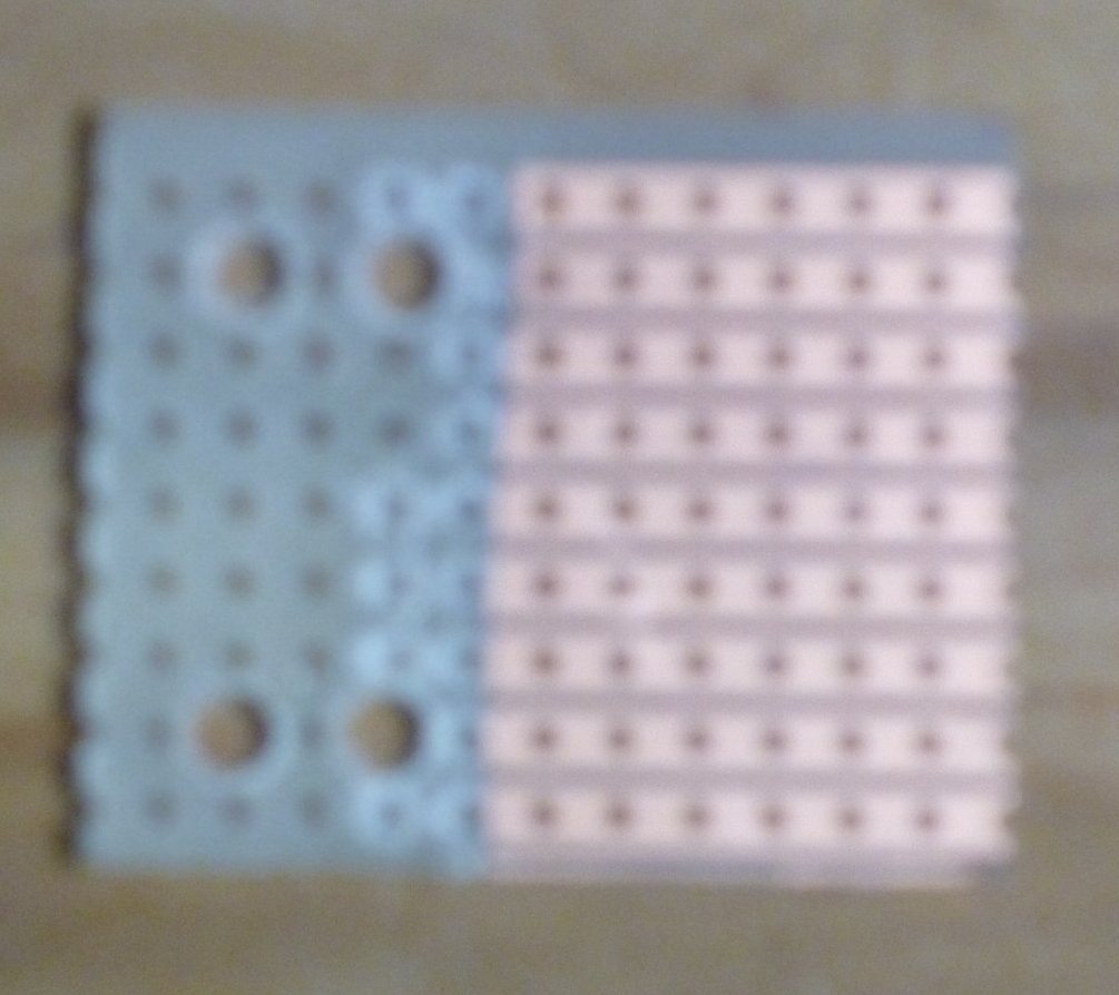
Signal Connector Board, holes drilled
Nine conductor ribbon cables (DigiKey part number MC09G-25-ND) is used to connect between the Signal Driver Board and the signals. One end gets a 9-pin header plug and the other end gets a small circuit board with small screw terminals. The actual LEDs in the signals are connected to wire wrap wire, but wire wrap wire is too delicate to run long distances, but is needed to fit in the small brass tubes the signal targets are mounted on. Once under the layout bench-work, the wire wrap wire gets connected with screw terminals to the much more robust ribbon cable. The small circuit boards are again made from pieces of strip-board, with nine strips, eleven holes long. After cutting the boards, some of the copper is removed and four 1/8 inch (3.5mm) holes are drilled.
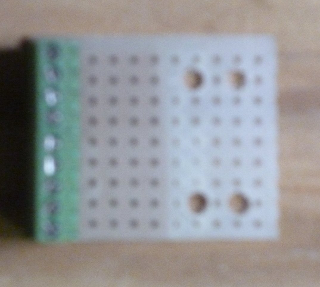
Signal Connector Board, terminal blocks installed
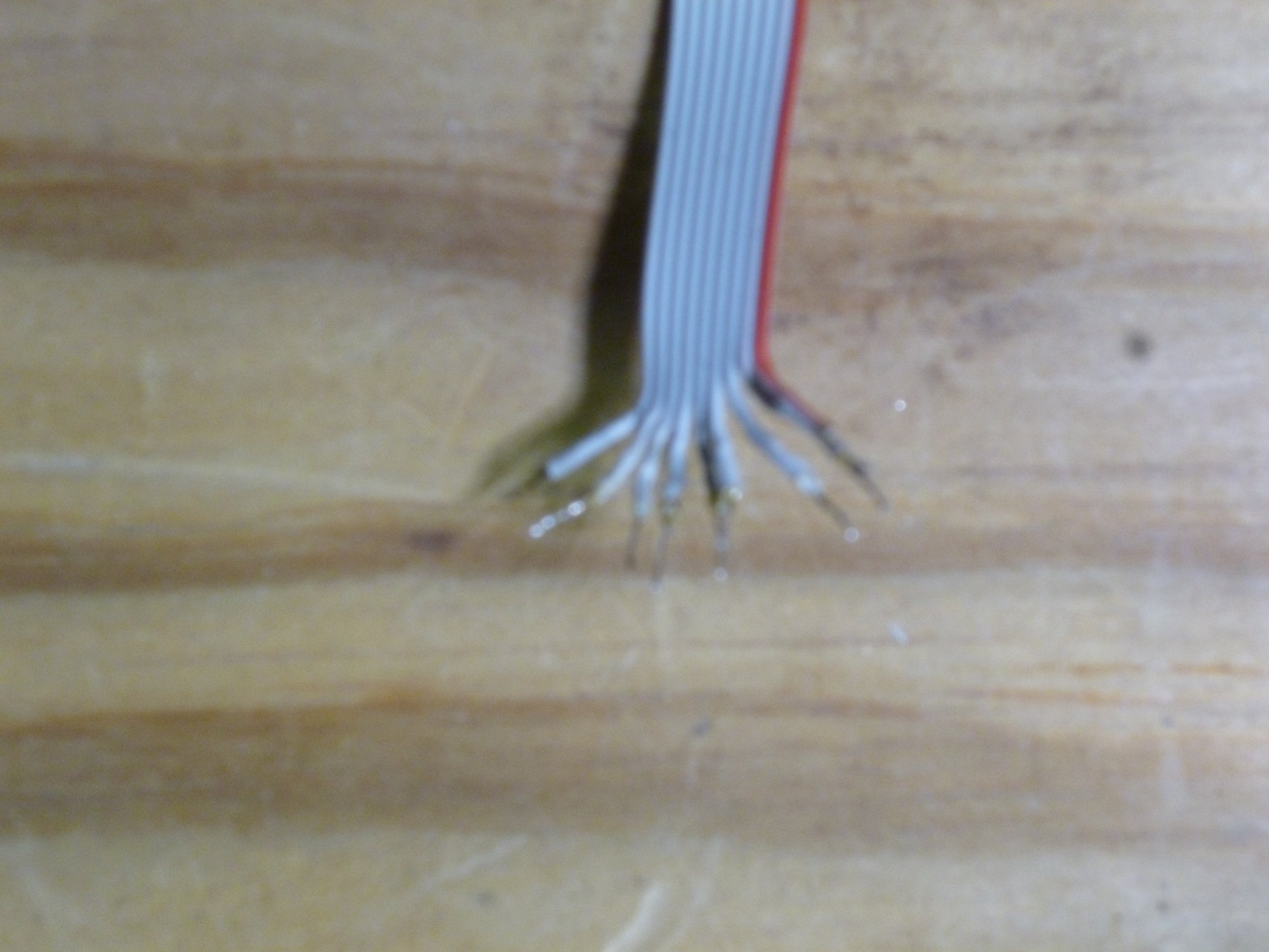
Signal Connector Cable, wires stripped and tinned
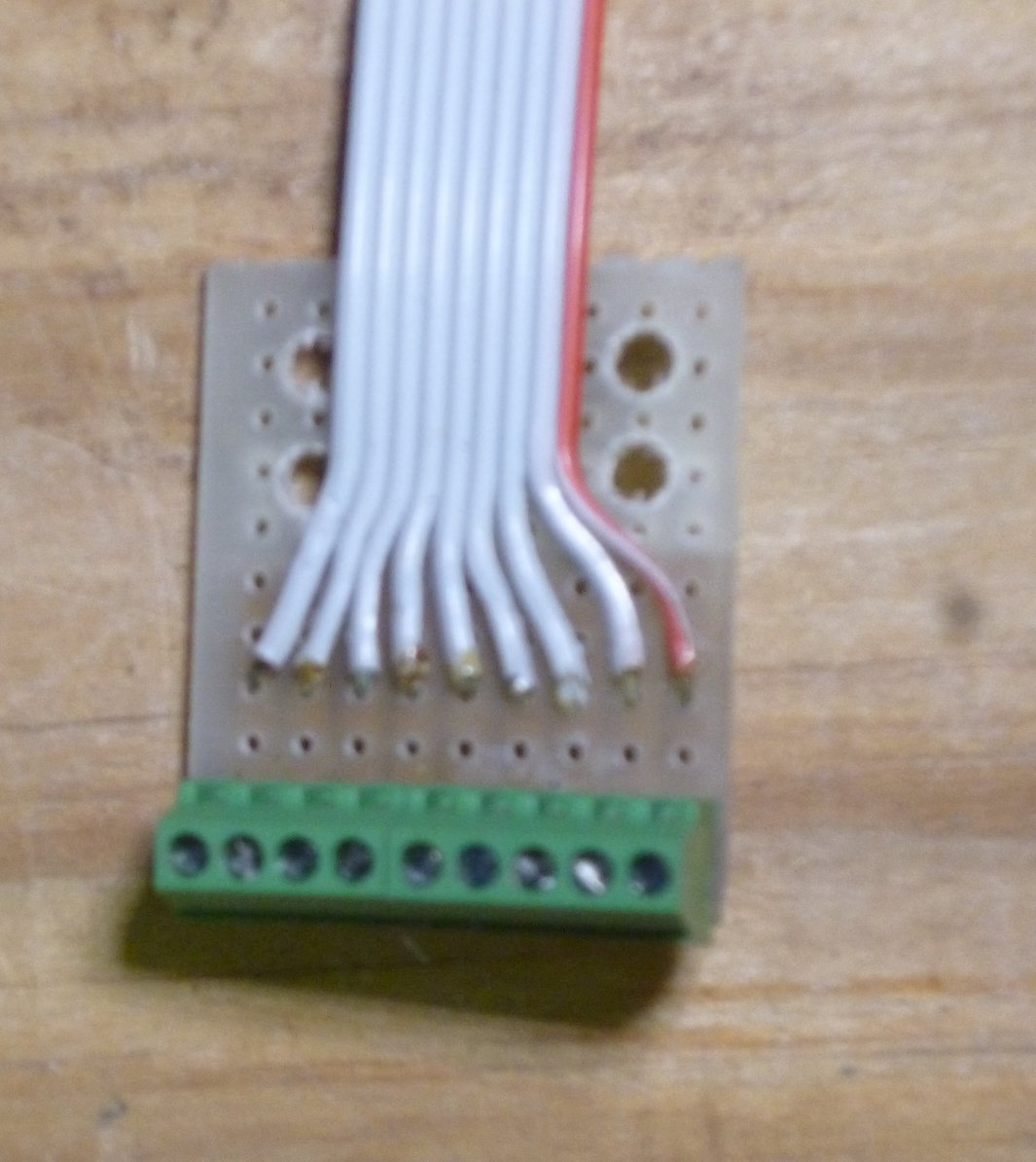
Signal Connector Board, cable soldered on
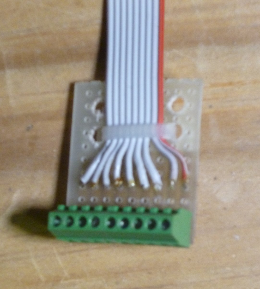
Signal Connector Board, cable secured with wire tie
Next the screw terminal blocks are soldered to the board (this is actually a 4 position terminal block with a 5 position terminal block next to it — Mouser does not stock the 9 position version of these terminal blocks). Then the conductors at one end of the cable is zipped back about a 3/4 inch (18mm) and about 1/4 inch (6mm) of the ends are stripped and tinned. These tinned conductors are then fed into holes in the circuit board and soldered. Finally a wire tie is used to secure the cable and act as a strain relief.
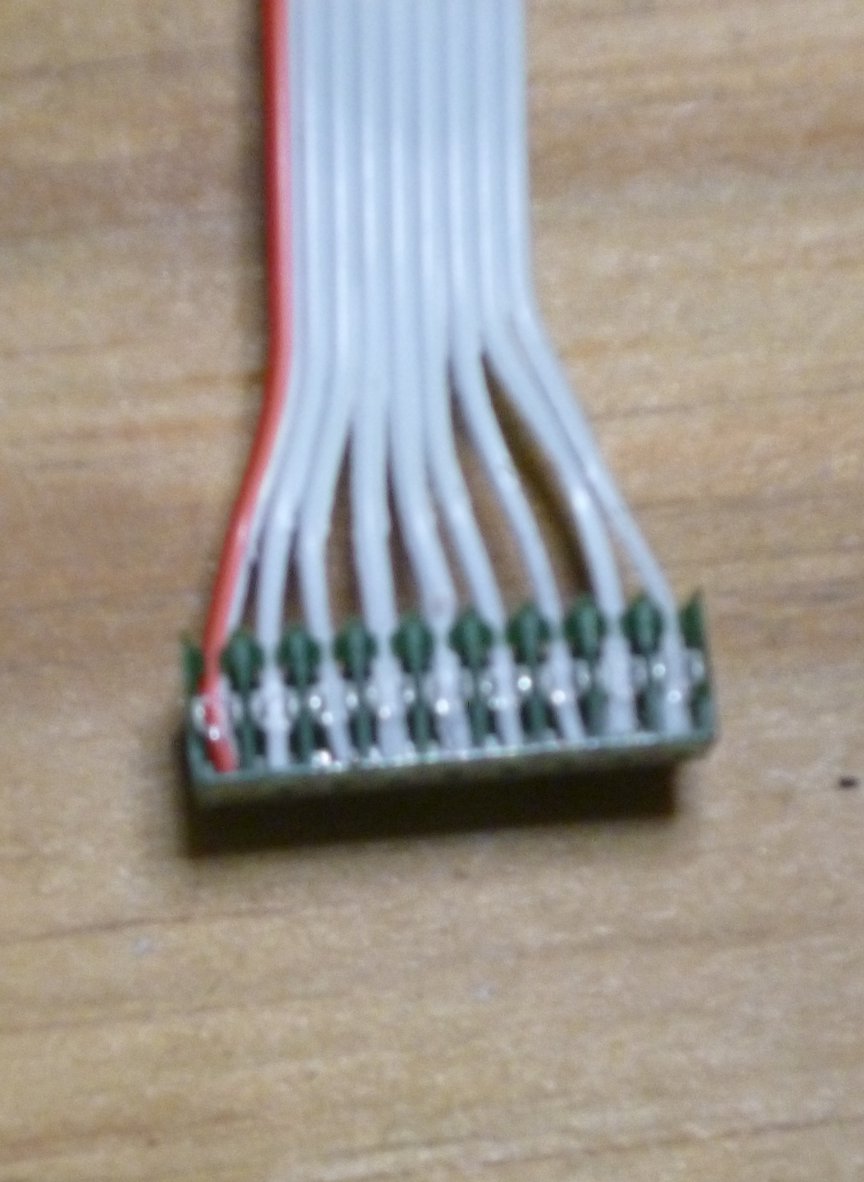
Signal Connector Cable, header plug installed
Finally, a 9 position header plug is installed on the other end of the cable.
About cable lengths: each cable should be long enough to reach from where the signal wire bundles emerge under the layout to where the Signal Driver Board is mounted. It is always better to cut the ribbon cables longer than needed since excess cable can be managed in various ways, but a short cable is not useable. The length of the wire wrap wires should be as short as you can get away with, which means the terminal block ends should be as close as possible to the place where the signal wire bundles emerge under the layout.
Continuing with Model RR signals with an Arduino, Assembling signal targets.