
The code to download to the Arduino is in available for download as SignalDriverMax72xx_Ardunio.zip. It uses the LedControl library, so the code starts by including the header file:
#include <LedControl.h>
Then since it is using scanf() and various string function, it includes stdio.h and string.h:
#include <stdio.h>

#include <string.h>
Then it allocates a LedControl object:
/*

* Create a new LedControl.

* We use pins 12,11 and 10 for the SPI interface

* With our hardware we have connected pin 12 to the DATA IN-pin (1) of the first MAX7221

* pin 11 is connected to the CLK-pin(13) of the first MAX7221

* pin 10 is connected to the LOAD-pin(12) of the first MAX7221

* We will only have a single MAX7221 attached to the arduino

*/

LedControl lc1=LedControl(12,11,10,1);
Next the setup function initializes the MAX72xx chip and sends an announcement to the host computer over the serial port:
void setup() {

/* Set max intensity */

lc1.setIntensity(0,15);

/* Set all signals to 'dark' (no lights on). */

lc1.clearDisplay(0);

/* Wake up display. */

lc1.shutdown(0,false);

/* Announce ourself to the host */

Serial.begin(115200);

Serial.println("Signal Driver Max72XX 0.0");

Serial.print("\n>>");

Serial.flush();

}
Next the signal aspects are defined. These values assuming that the signal heads are wired bottom to top, with the LEDs wired from bit 0 to 5 as: lower red, lower yellow, lower green, upper red, upper yellow, and upper green. (See Wiring the signals below.)
/* Signal Aspects */

#define R_R B00001001 /* Red over Red (Stop) */

#define R_Y B00001010 /* Red over Yellow (Approach Limited) */

#define R_G B00001100 /* Red over Green (Slow Clear) */

#define Y_R B00010001 /* Yellow over Red (Approach) */

#define G_R B00100001 /* Green over red (Clear) */

#define DARK B00000000 /* Dark (all lights off) */
Next we have a helper function to convert from an aspect name sent from the host computer to the Arduino.
int GetAspectBits(const char *aspectname) {

/** Test for each signal aspect string and when a match

* Occurs, return the corresponding bit pattern. */

if (strcasecmp("R_R",aspectname) == 0) return R_R;

else if (strcasecmp("R_Y",aspectname) == 0) return R_Y;

else if (strcasecmp("R_G",aspectname) == 0) return R_G;

else if (strcasecmp("Y_R",aspectname) == 0) return Y_R;

else if (strcasecmp("G_R",aspectname) == 0) return G_R;

else if (strcasecmp("DARK",aspectname) == 0) return DARK;

else return -1;

}
Next comes the main loop function. Here we read a one line command from the host computer and decide what to do. There are only two commands defined, one to turn all of the LEDs off and another to set the aspect of one signal.
void loop() {

char buffer[256]; /* Command line buffer. */

int  len;         /* Line length. */
/* If there is serial data available... */

if (Serial.available() > 0) {

/* Read a line from the serial port (USB connection

from the host computer. */

len = Serial.readBytesUntil('\r',buffer,sizeof(buffer)-1);

if (len <= 1) {

/* Reissue command prompt. */

Serial.print("\n>>");

Serial.flush();

return;

}

buffer[len] = '\0';

switch (toupper(buffer[0])) {

case 'D': /* Clear all signals to Dark. */

lc1.clearDisplay(0);

break;

case 'S': /* Set one signal. */

{

char unused;

char aspect[10];

int  signalnum, aspectbits;

if (sscanf(buffer,"%c %d %9s",&unused,&signalnum,aspect) != 3) {

Serial.println("\nSyntax error (Set command)!");

} else {

/* Parse aspect string. */

aspectbits = GetAspectBits(aspect);

/* Check for legal aspect string. */

if (aspectbits < 0) {

Serial.println("\nSyntax error (Bad aspect)!");

/* Check for legal signal number. */

} else if (signalnum >= 0 && signalnum < 8) {

lc1.setRow(0, signalnum, (byte) aspectbits);

} else {

Serial.println("\nSyntax error (Bad signal number)!");

}

}

break;

}

default:

Serial.println("\nUnknown command!");

break;

}

/* Reissue command prompt. */

Serial.print("\n>>");

Serial.flush();

}

}
Wiring the signals.
I used this color coding for the signal LEDs when I wired them:
- Green
- The upper target head’s green LED (uppermost LED of the upper target).
- Yellow
- The upper target head’s yellow LED (middle LED of the upper target).
- Red
- The upper target head’s red LED (bottom LED of the upper target).
- Blue
- The lower target head’s green LED (uppermost LED of the lower target).
- White
- The lower target head’s yellow LED (middle LED of the lower target).
- Black
- The lower target head’s red LED (bottom LED of the lower target).
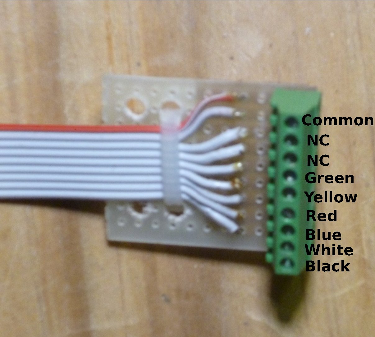
Signal Connector Board, Wiring Color Codes
Thus the connections to the terminal blocks at the ends of the signal cables are made as shown here. If a target has fewer than three LEDs, then the wires for the missing LEDs are also missing.
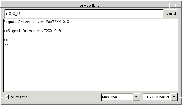
Serial Monitor, Test Sketch
Once you have entered the code and verified that it compiles and uploaded it to the Arduino, you can test the code with the Serial Monitor tool on the Arduino IDE. Be sure to set the baud rate to 115200. You can then type commands into the Serial Monitor tool’s send bar, as shown here.
Addendum:
I have updated the firmware to include a “Test” command. This command can be used to test signals. It runs though a sequence of patterns, lighting the LEDs in the selected signals. There are three forms for this command:
TWith no arguments, all eight signals are tested in sequence.T nWith one argument, the selected signal number is tested.T n mWith two arguments, the range of signals are tested.
The updated code is in this zip file:SignalDriverMax72xx_Ardunio-0.1
Continuing with Model RR signals with an Arduino, Programming the host computer.