
I will be building an interlocking plant module with 5 two-headed signals. To drive all of these signals I will be using an Arduino and a Max72XX Led driver (see http://playground.arduino.cc/Main/MAX72XXHardware for more information about general uses for the Arduino and the Max72XX chips). This article describes the hardware involved, the firmware (software on the Arduino) and the host computer software (using the Dispatcher program from my Model Railroad System).
The layout module
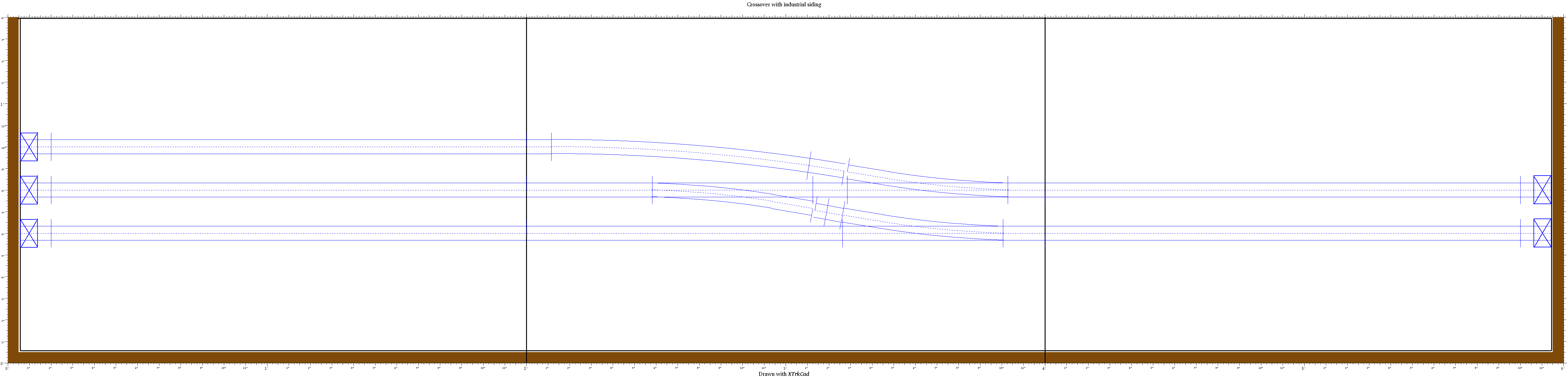 The layout module is a simple double track main line with a single crossover and an industrial siding, as shown here. There will be a two-track signal bridge (Oregon Rail Supply #151) at the east (right) end of the interlocking plant and a three-track signal bridge (Oregon Rail Supply #154, cut down to three tracks) at the west (left) end of the interlocking plant. At the east end will be a 3 over 2 on track 1 (upper/north main line) and a 3 over 3 on track 2 (lower/south main line). At the west end will be a 1 over 3 on the siding exit, a 3 over 3 on track 1 (upper/north main line) and a 3 over 1 on track 2 (lower/south main line).
Hardware being used
I will be using Oregon Rail Supply signal bridges, one 2-track (#151) and one 4-track (#154, cut down to 3-tracks). I will be using 2mm x 1.25mm chip LEDs (Mouser part numbers 720-LGR971-KN-1, 720-LYR976-PS-36, and 720-LSR976-NR-1) on small circuit boards to light these signals. There will be an Arduino Uno (Mouser part number 782-A000066) and a home built board (based on the Arduino Playground circuit) containing a Max7221 (Mouser Parts: Mouser Project and PCB Layout/assembly). This article describes how I built these signals and how I will control them from my Linux computer, using a CTC panel created with my Model Railroad System Dispatcher program.
Continuing with Model RR signals with an Arduino, Signal Driver board.