This gallery contains 15 photos.
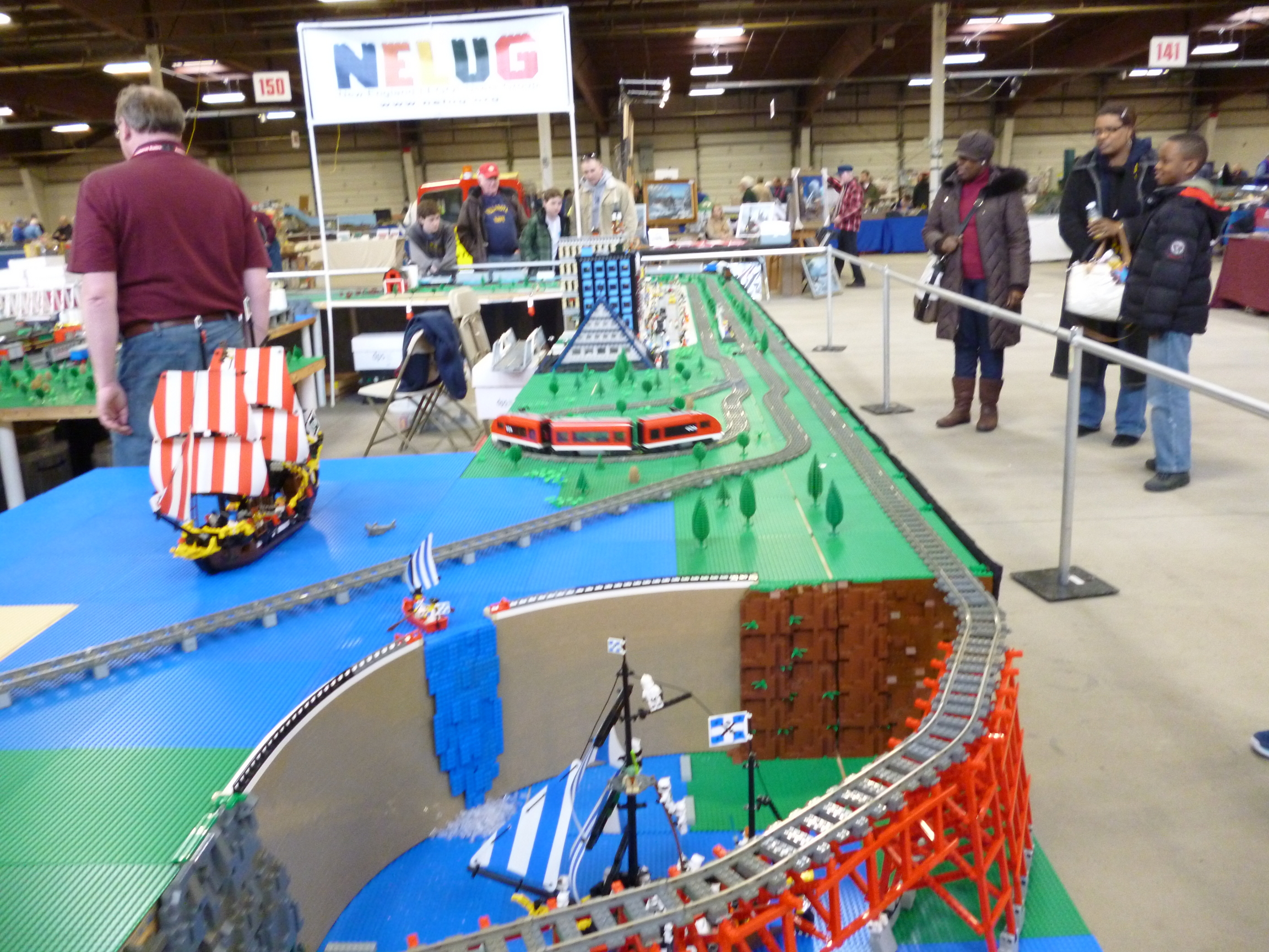
I addended the Amherst Railway Show last Saturday. Here are some of the pictures and videos I took.

Model railroading.
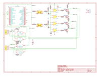
The hardware I have designed an add on circuit board for the Raspberry Pi to control stall motor turnout motors. This board uses a quad op-amp circuit to drive a quad output transistor to drive the motors. It also features a 74AHCT00 Quad 2-input Nand Gate IC, wired as a…
The code to download to the Arduino is in available for download as SignalDriverMax72xx_Ardunio.zip. It uses the LedControl library, so the code starts by including the header file: #include <LedControl.h> Then since it is using scanf() and various string function, it includes stdio.h and string.h: #include <stdio.h> #include <string.h> Then…
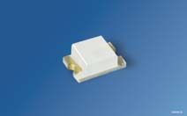
The next step is to assemble the signal targets. I used 2mm x 1.25mm chip LEDs, made by Osram and sold by Mouser (part numbers Green: 720-LGR971-KN-1, Yellow: 720-LYR976-PS-36, and Super Red: 720-LSR976-NR-1). These are $.10 each in single quantities and the price goes down to about five and a…
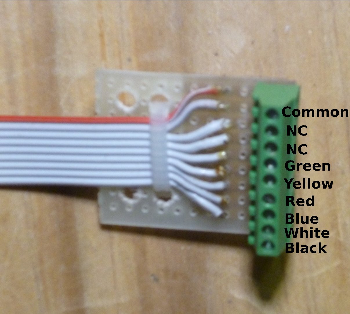
Nine conductor ribbon cables (DigiKey part number MC09G-25-ND) is used to connect between the Signal Driver Board and the signals. One end gets a 9-pin header plug and the other end gets a small circuit board with small screw terminals. The actual LEDs in the signals are connected to wire…
The Signal Driver board is connected with a home made connector cable. The cable is a six conductor ribbon cable (DigiKey part number MC06G-25-ND). One end of the cable is attached to a 6-pin .1 inch (2.54mm) IDC header plug and the other end connected to a "plug" made from…
The Signal Driver board is assembled on a piece of "strip board", specifically a 3.5 inch by 2.5 inch piece cut from a BusBoard Prototype Systems BPS-MAR-ST6U-001 (included in the Mouser project). After cutting this piece from the board some of the copper foil needs to be carefully removed. This…
I will be building an interlocking plant module with 5 two-headed signals. To drive all of these signals I will be using an Arduino and a Max72XX Led driver (see http://playground.arduino.cc/Main/MAX72XXHardware for more information about general uses for the Arduino and the Max72XX chips). This article describes the hardware involved,…
This gallery contains 15 photos.
I addended the Amherst Railway Show last Saturday. Here are some of the pictures and videos I took.
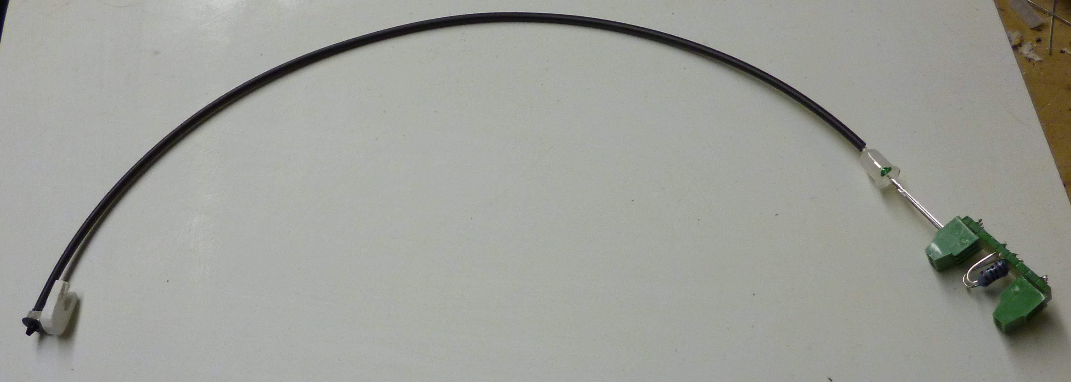
I have assembled the N scale signals for the Two Siding Oval layout. This assembly consists of a BLMA Models #1000 non-operating N Signal Head (mounted on a piece of styrene), a length of fiber optic cable (Mouser #630-HFBR-RNS001Z), a two color (red/green) LED (Mouser # 696-SSLLX5099GIWCA), and a small…
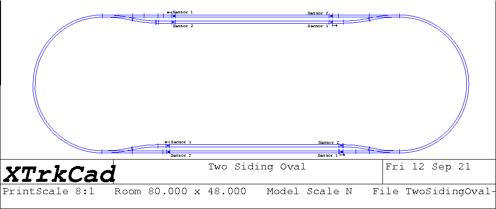
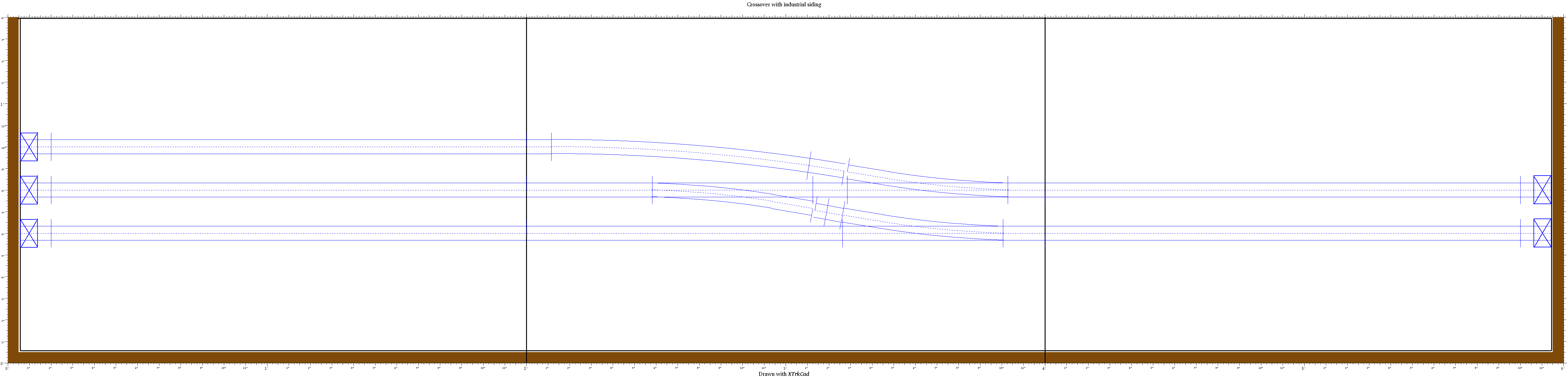
I am about to build a pair of demo Model Railroad layout modules: A 2’x6′ N scale oval layout, with a pair of passing sidings. This layout is designed to run two trains in opposite directions. It will be automated using a computer (using parts of the Model Railroad System),…