
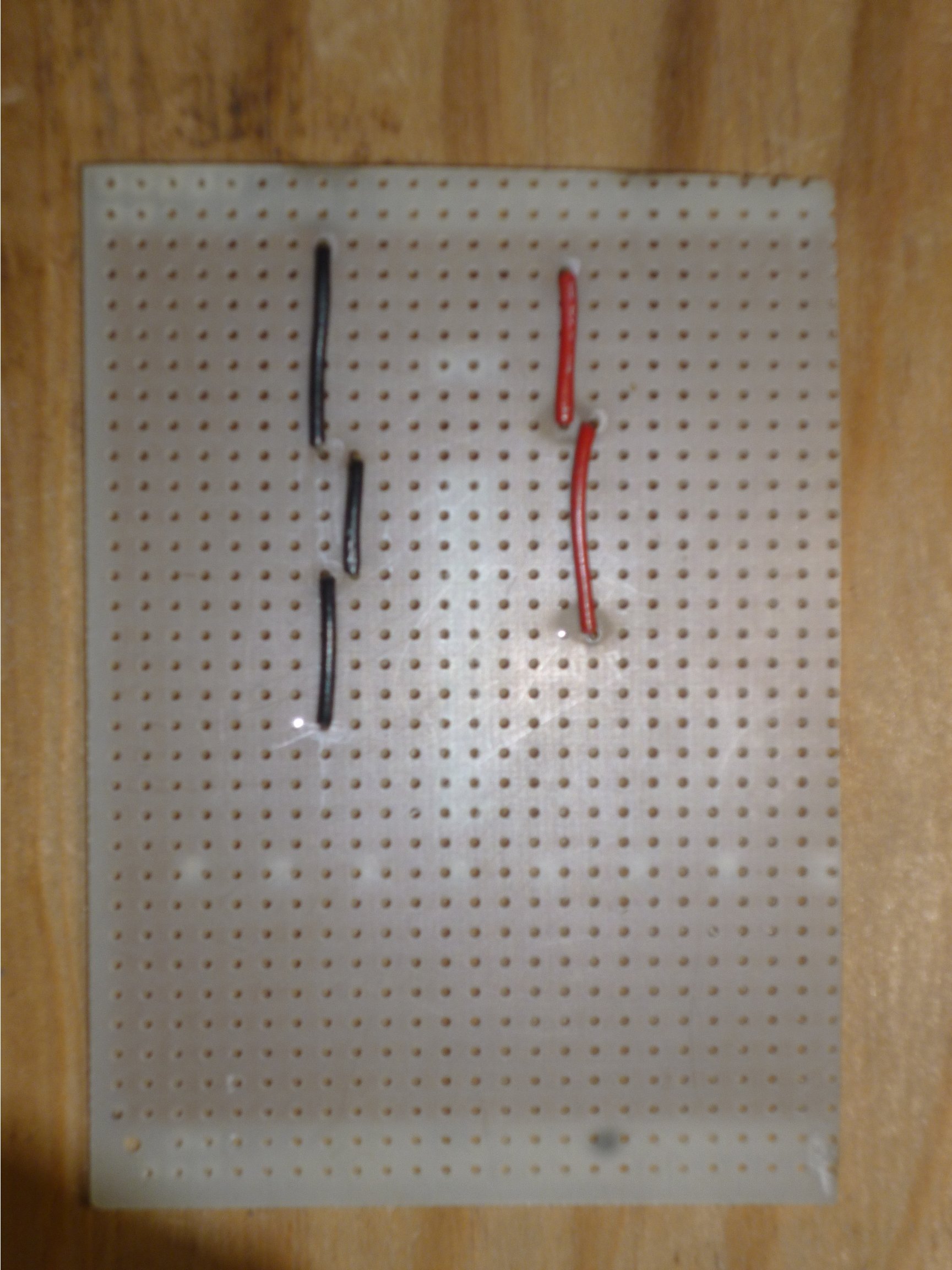
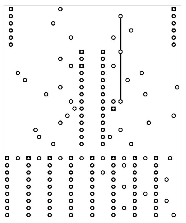
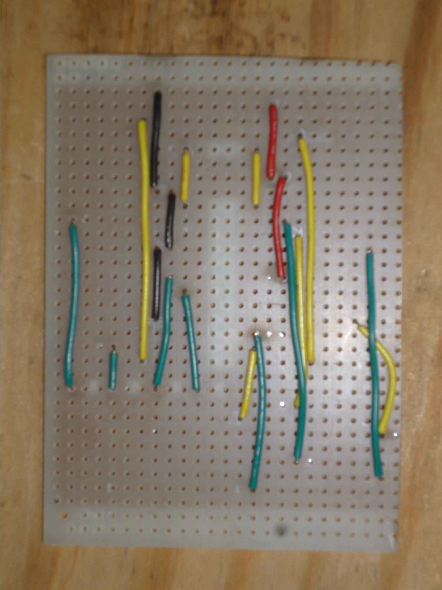
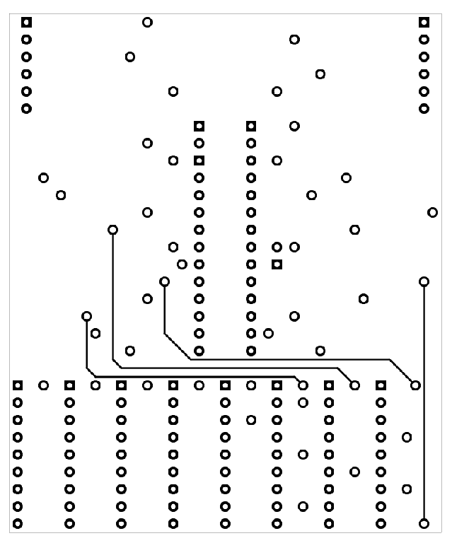
The Signal Driver board is assembled on a piece of "strip board", specifically a 3.5 inch by 2.5 inch piece cut from a BusBoard Prototype Systems BPS-MAR-ST6U-001 (included in the Mouser project). After cutting this piece from the board some of the copper foil needs to be carefully removed. This is done with a sharp hobby knife and a soldering iron is used to heat the copper to make it easy to peel. The PCB Layout/assembly Zip file includes a PostScript file named SignalDriverMax72xx.back.ps which is an actual sized drawing of what the foil should look like. Here is a side-by-side view of an actual board and the SignalDriverMax72xx.back.ps drawing:
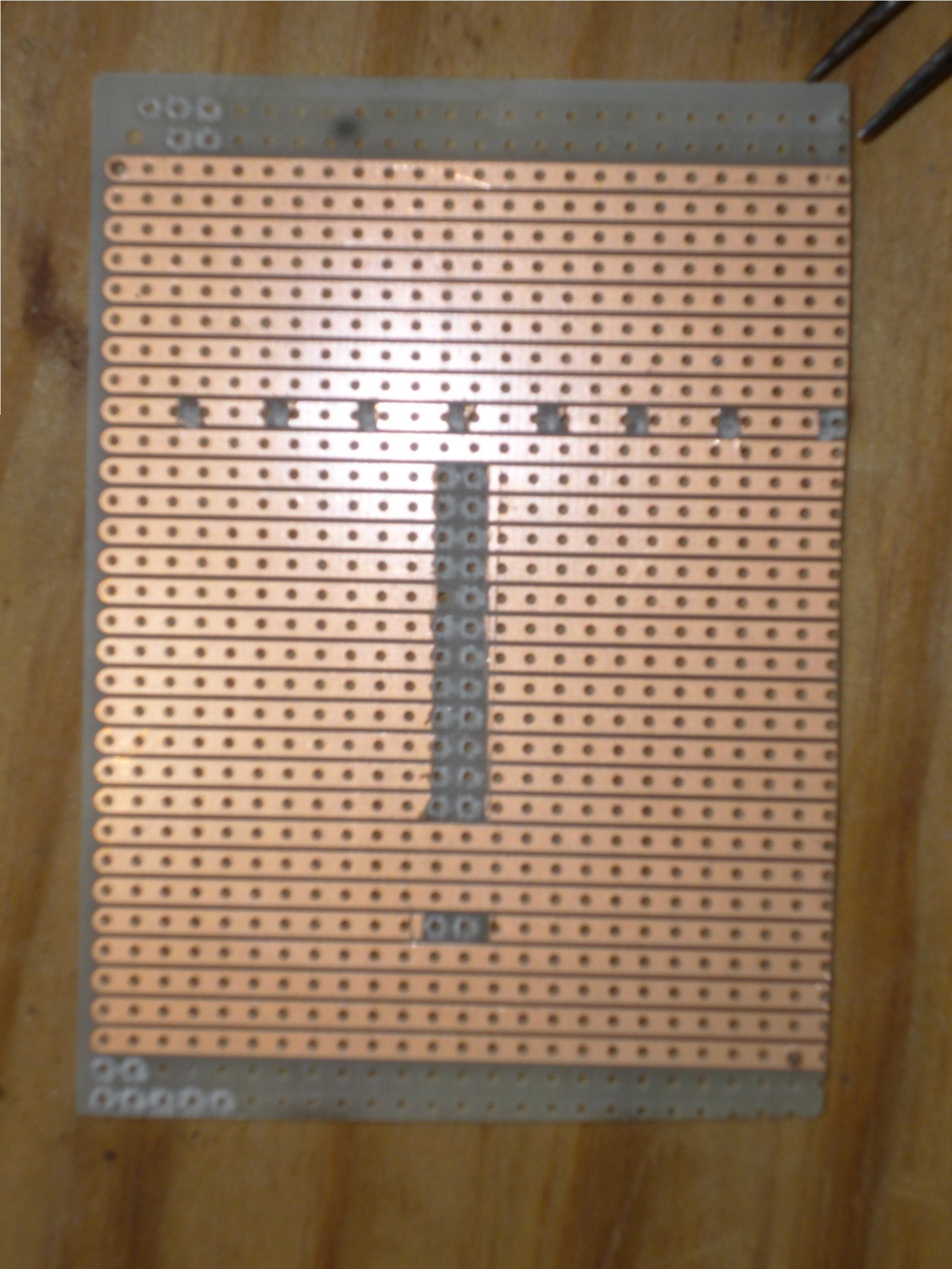
Photo of the Signal Driver circuit board (foil side)
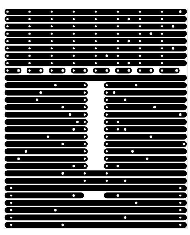
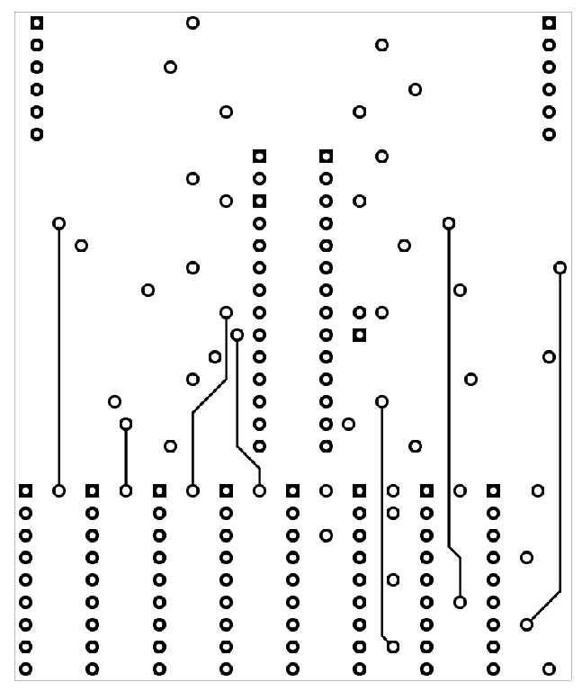
Signal Driver Foil side PCB layout
I cut the board to have two strip rows above and below the foil layout to provide a place to drill mounting holes that would not interfere with the circuit elements.
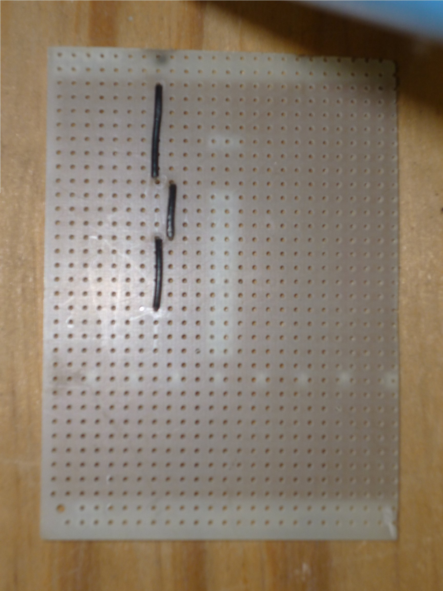
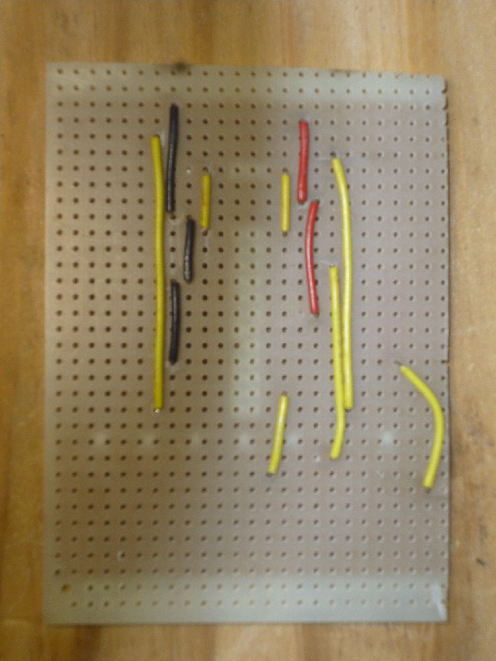
Photo of group2 (ground) wires in black
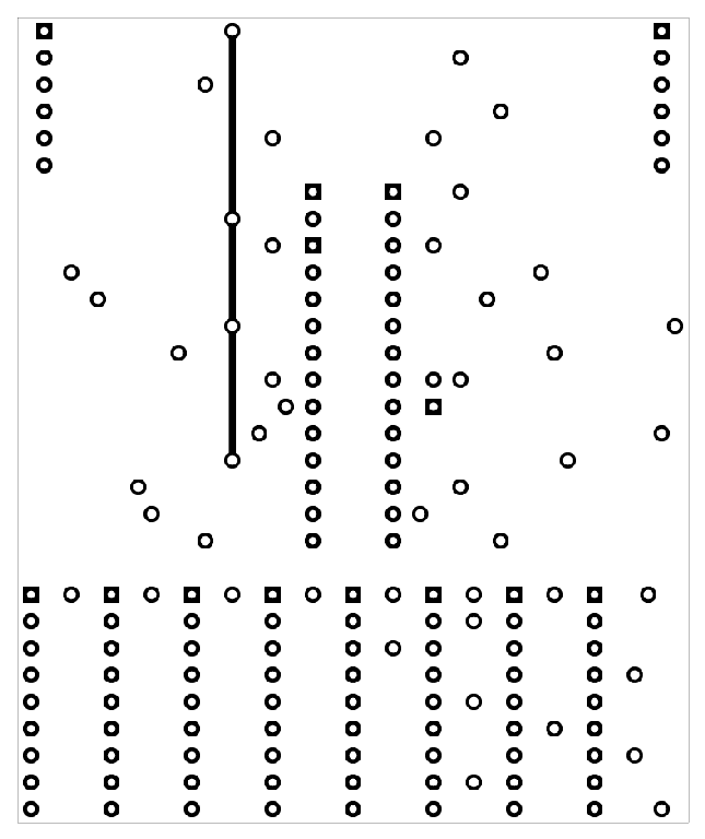
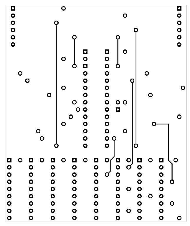
Group2 (ground) PCB Layout
The next step is to run the vertical connections, using solid hookup wire. I used a different color for each "layer". Staring with layer group2 (ground) in black.
Group3 (power) with red wire
Group3 (power) PCB Layout
Then layer group3 (power) in red.
Group4 (signal1) in Yellow
Group4 (signal1) PCB Layout
Then layer group4 (signal1) in yellow.
Group5 (signal 2) in green
PCB layer group5 (signal2)
Then layer group5 (signal2) in green.
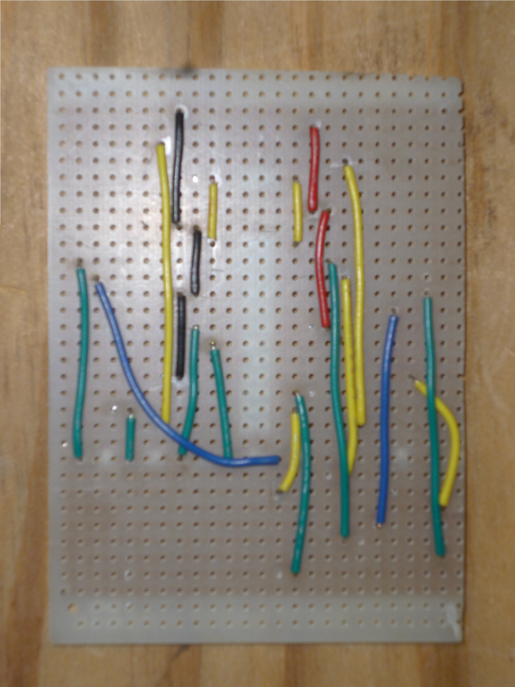
Photo of group6 (signal3) in blue.
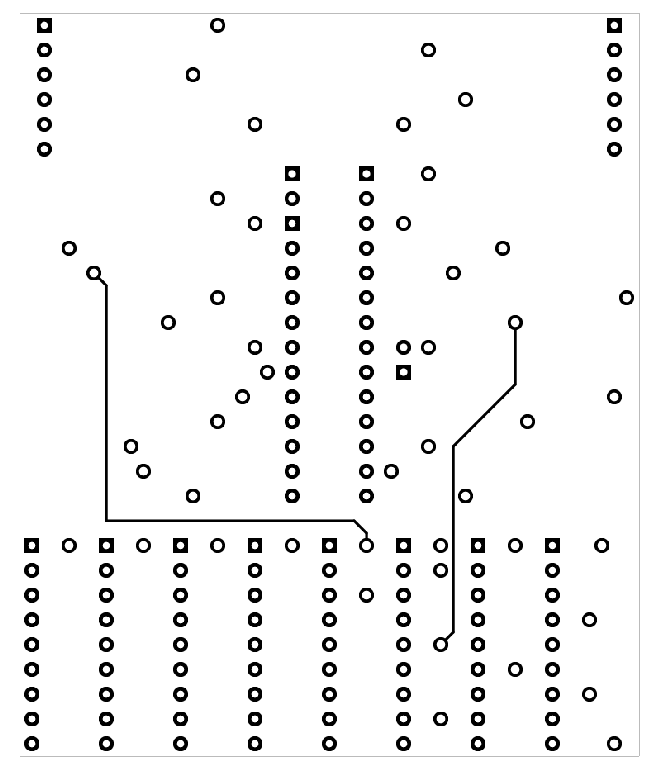
PCB layer group6 (signal3)
Then layer group6 (signal3) in blue.
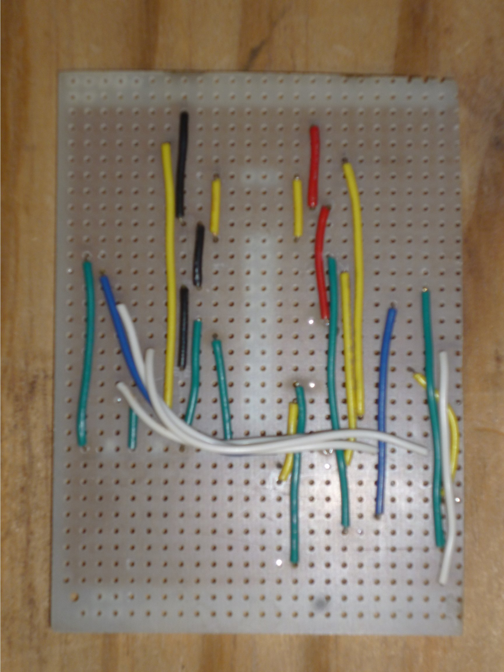
Photo of group 7 (signal 4) in white
PCB layout of group7 (signal4)
Then layer group7 (signal4) in white.
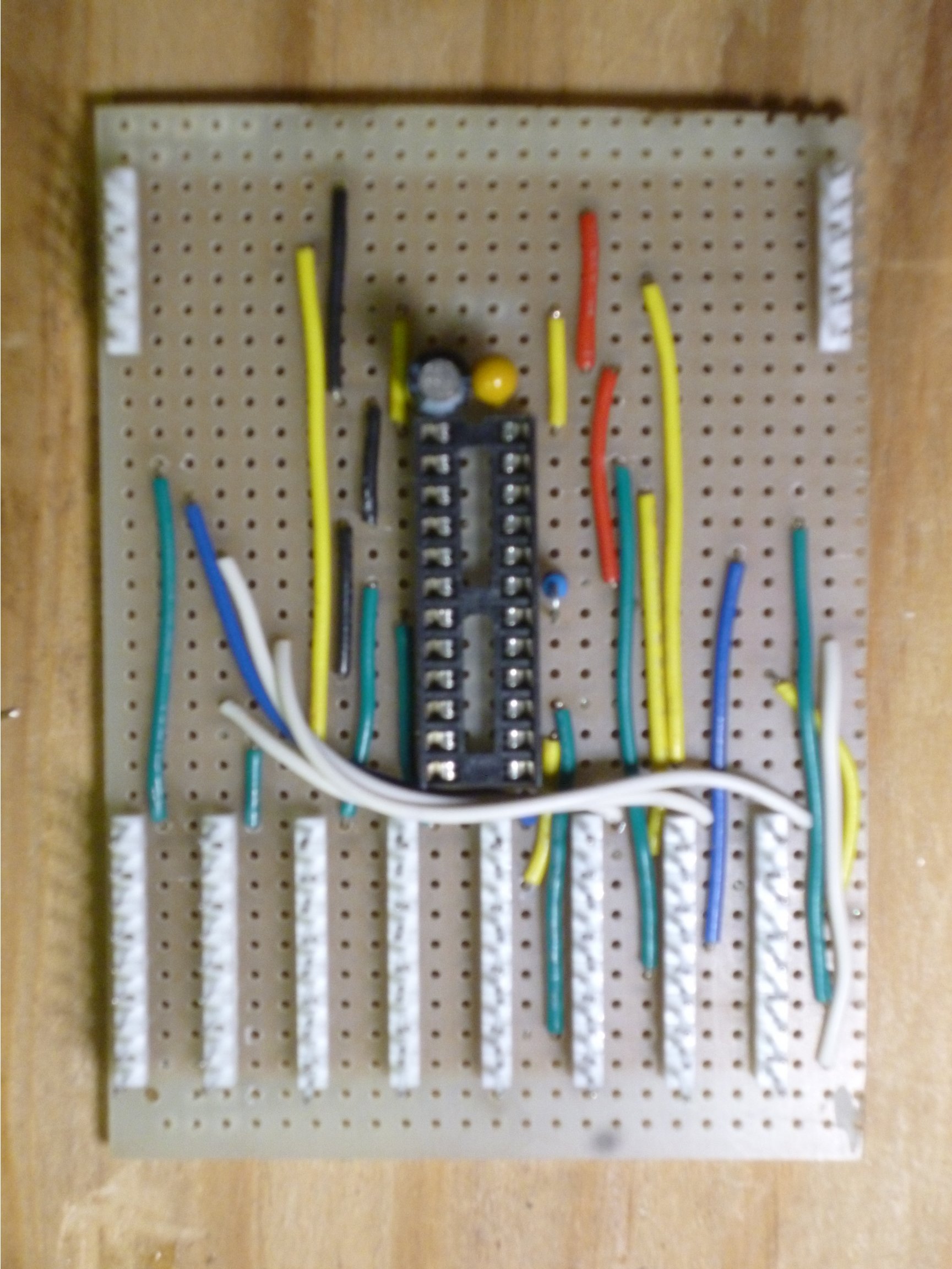
Photo of front assembly
PCB layout of front assembly
Finally, the headers, IC socket, and the passive components are installed. There is a trick to installing the IC socket and the headers: solder only one pin, then while pushing the socket or header against the board, reheat the solder to make it re-flow. This should cause the socket or header to snap squarely to the board. You might have to push some of the wires to one side to install the IC socket and the 9-pin headers, but if you were careful about routing the wires, this should not be a problem. The resistor needs to have one of its leads bent 180 degrees to allow it to be mounted on end. The unbent pin should go next to the where the red wires are installed. C2 (the larger electrolytic capacitor) is polarized. The negative lead (the shorter one next to the stripe) goes towards the IC socket. The resistor and the capacitors should be mounted as tightly to the board as possible. You can solder one lead and the reheat the solder to carefully position them tight and square.
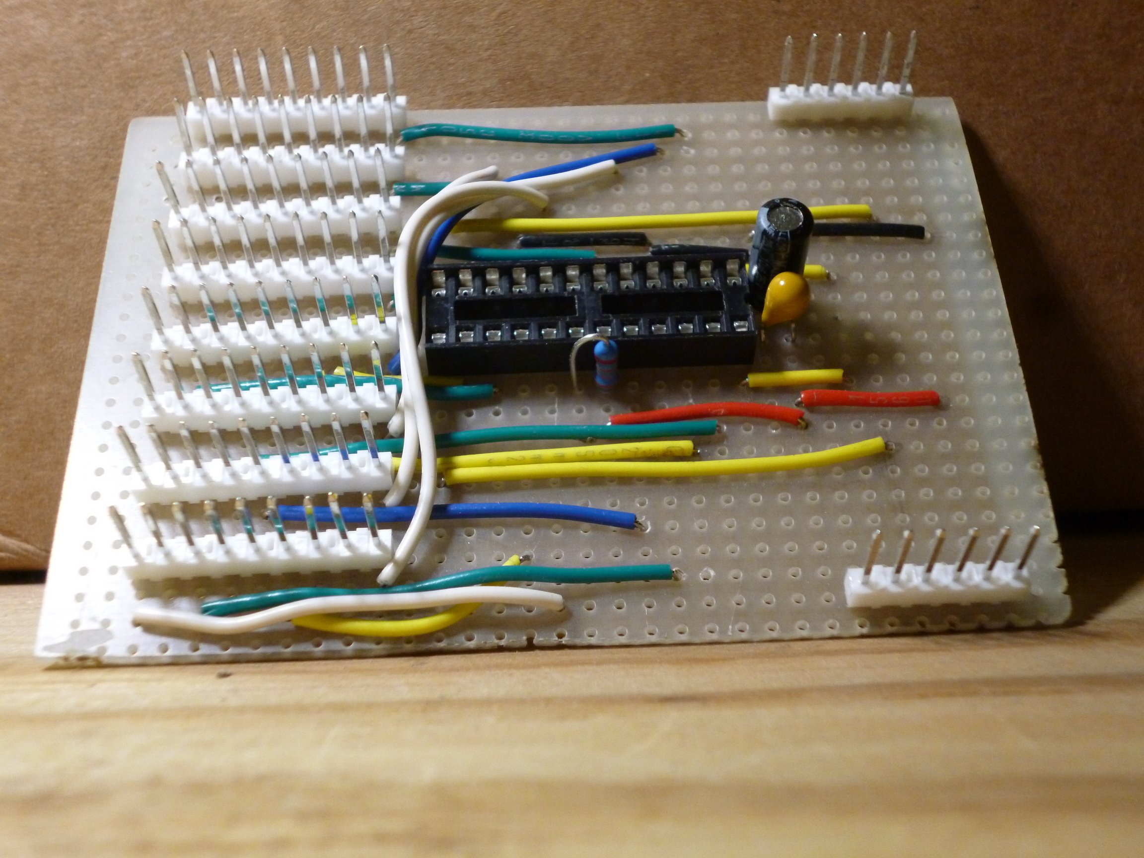
Photo of front assembly at an angle
Here is another view of the completed circuit board. This angle view gives a better view of the assembly. The next step is to carefully inspect the board, looking closely with a magnifier looking for solder bridges or bad solder joints.
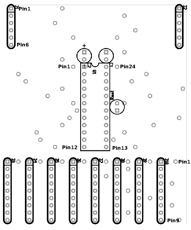
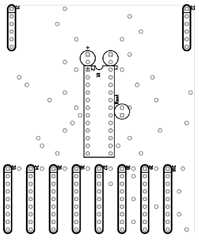
PCB layout of the front assembly with pin numbers
Then you can use an Ohmmeter (or a multimeter in Ohmmeter mode) to check the circuit paths from each pin of the IC socket. The text file named SignalDriverMax72xx.pcb.u1 in the PCB Layout/assembly zip-file contains a listing of the connections to each pin of the IC socket. Here is a version of the front assembly diagram with the pin numbers indicated.
Continuing with Model RR signals with an Arduino, Connecting the Signal Driver Board.