
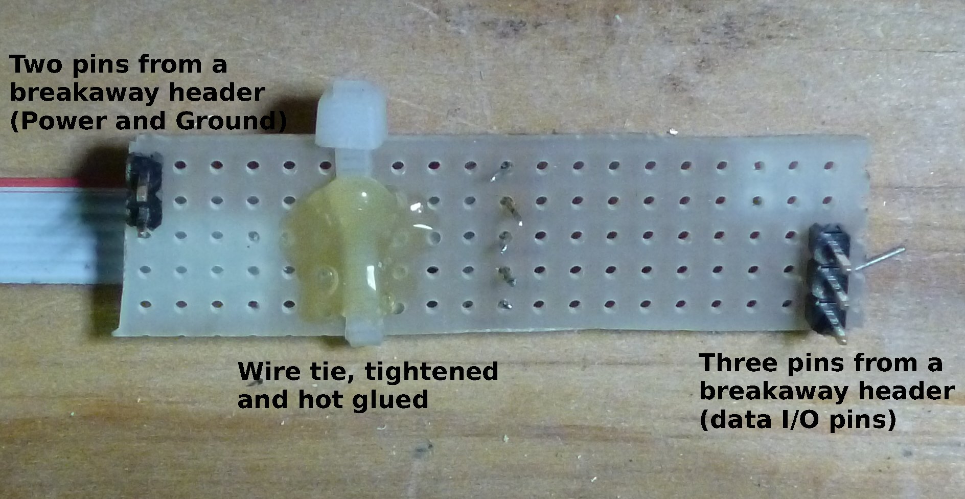
Component side of Uno connector
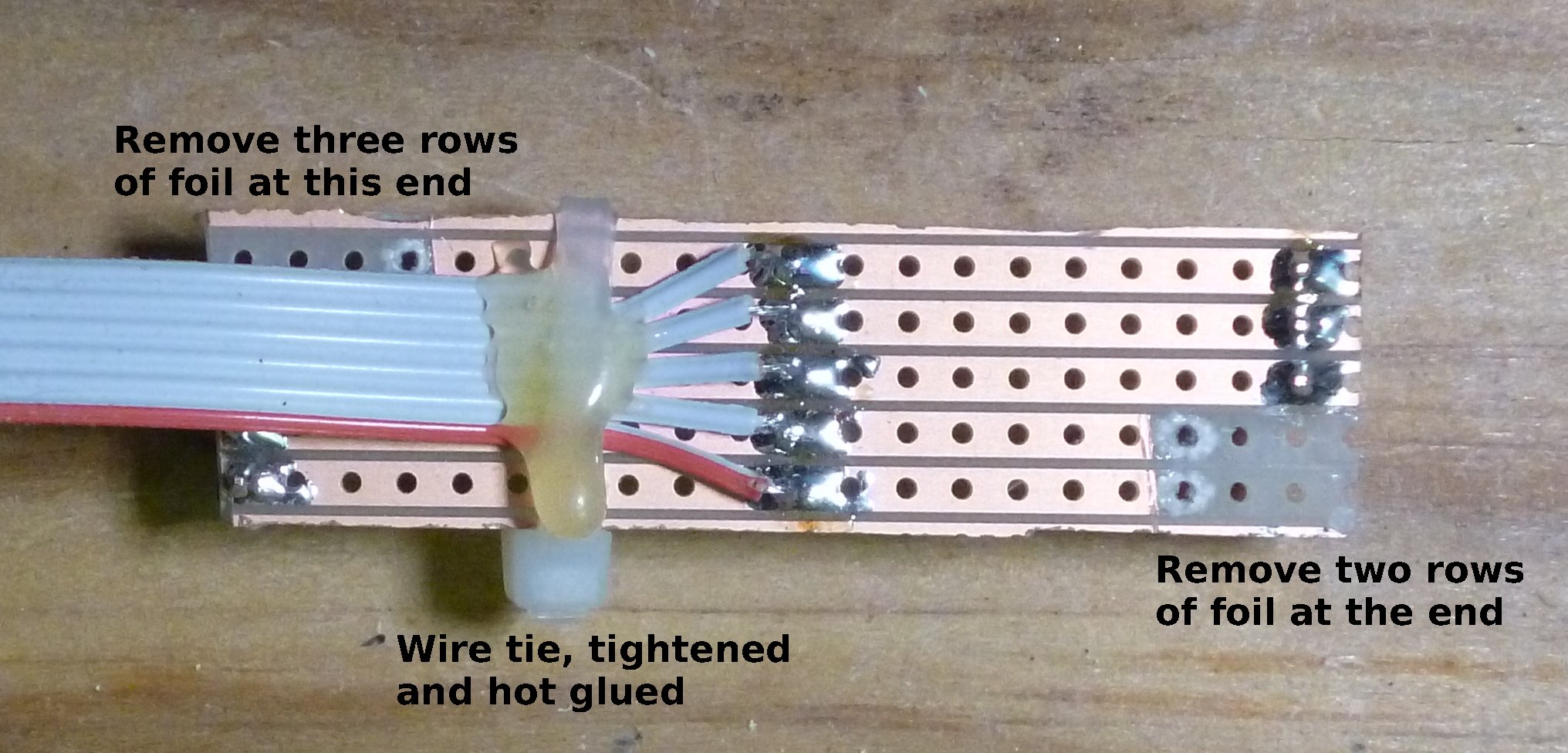
Uno Connector, Foil Side
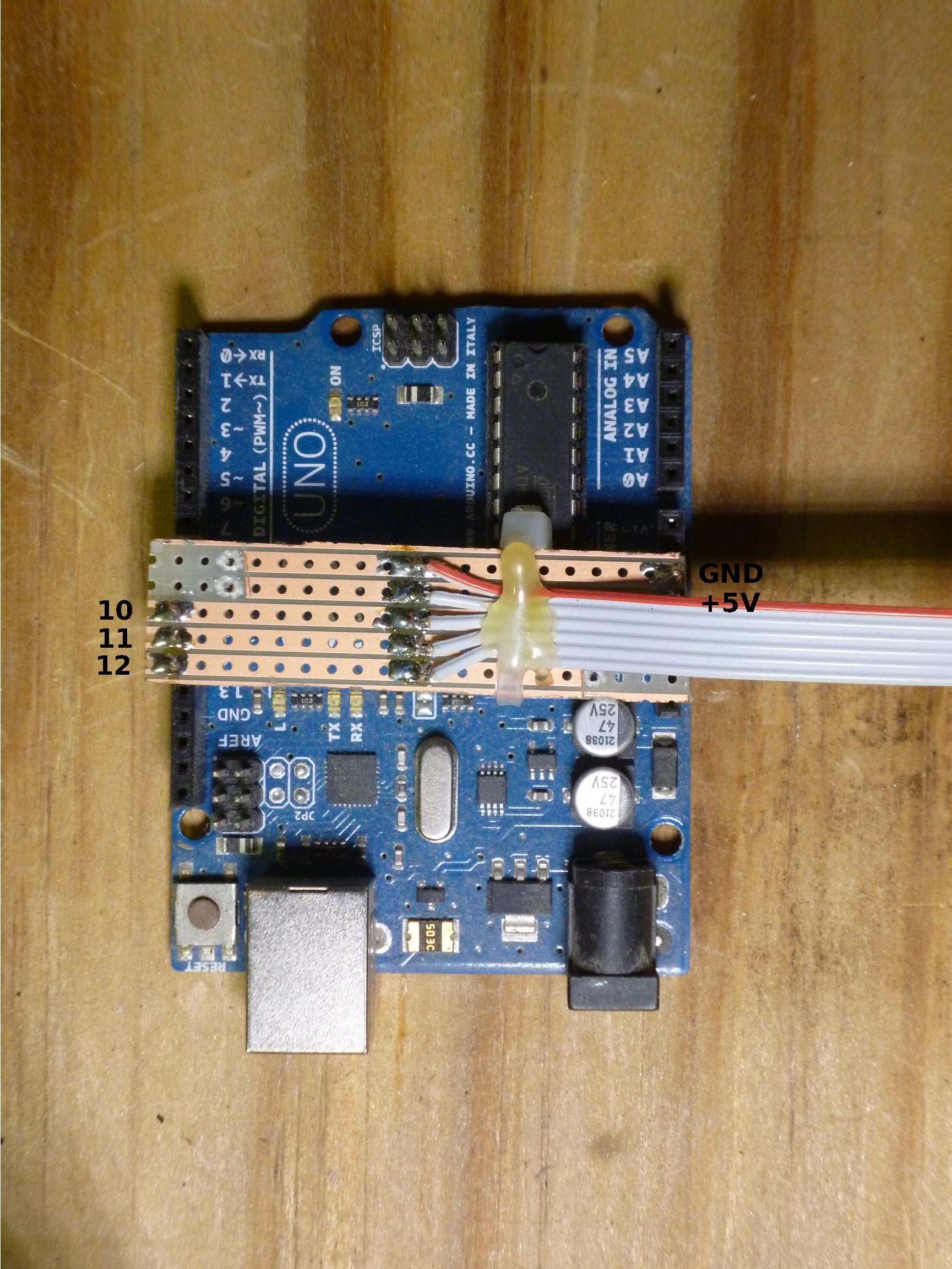
Connector on Uno
The Signal Driver board is connected with a home made connector cable. The cable is a six conductor ribbon cable (DigiKey part number MC06G-25-ND). One end of the cable is attached to a 6-pin .1 inch (2.54mm) IDC header plug and the other end connected to a "plug" made from a small piece of strip-board and a couple of pieces of .1 inch (2.54mm) pitch breakaway headers, 2 pins at the power and ground end and 3 pins at the digital I/O end. Some of foil should be removed (this prevents possible shorts). The cable is soldered to the foil side and the headers are mounted on the component side. The cable is secured with a wire tie and some hot glue. This connector fits on top of the Arduino Uno as shown. Make sure the pins are in the correct header position!
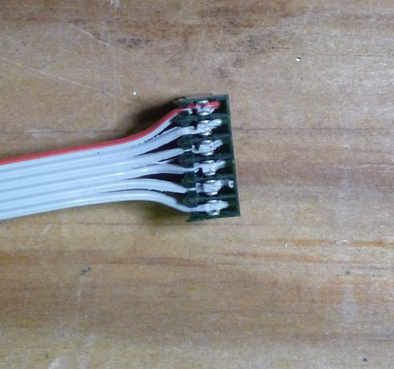
Connector Plug, Installed
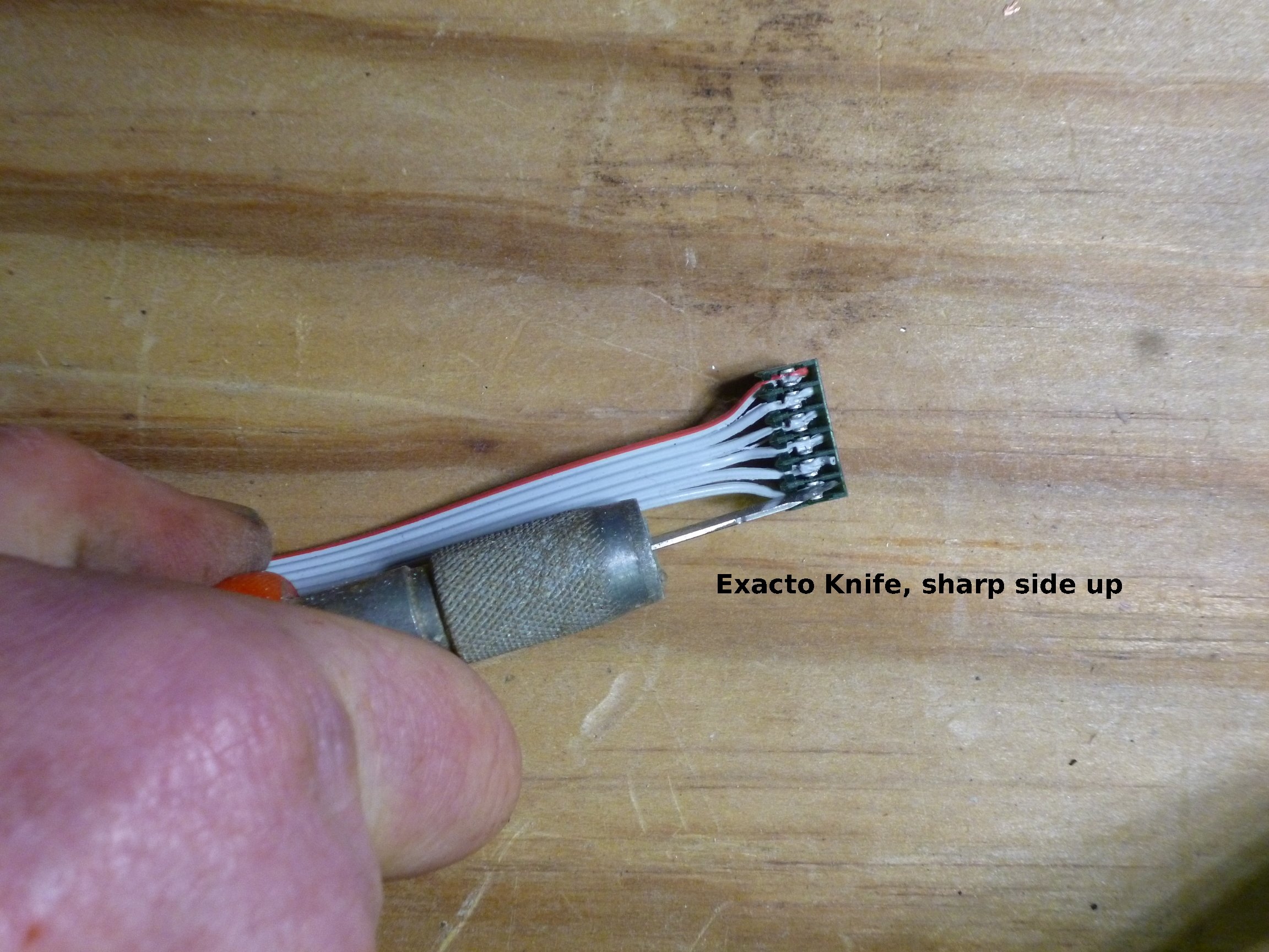
Installing Connector Plugs
The IDC plug is attached to the other end and I used an Exacto Knife to press the wires into the IDC slots. Mouser sells a $30 tool to do this, if you prefer.
Continuing with Model RR signals with an Arduino, Signal Driver board cables.